Module 3: Equipment, Inspection & Maintenance
Pump Spillback Lines and Operating Curves
A standard pump spillback line connects the pump discharge to the pump suction.
The purpose of the spillback line is to ensure the pump operates above its minimum flow.
The net fluid moved by the pump can be less than the minimum flow. With the spillback valve open, there is a very small "recycle" loop through the line from the discharge to the suction.
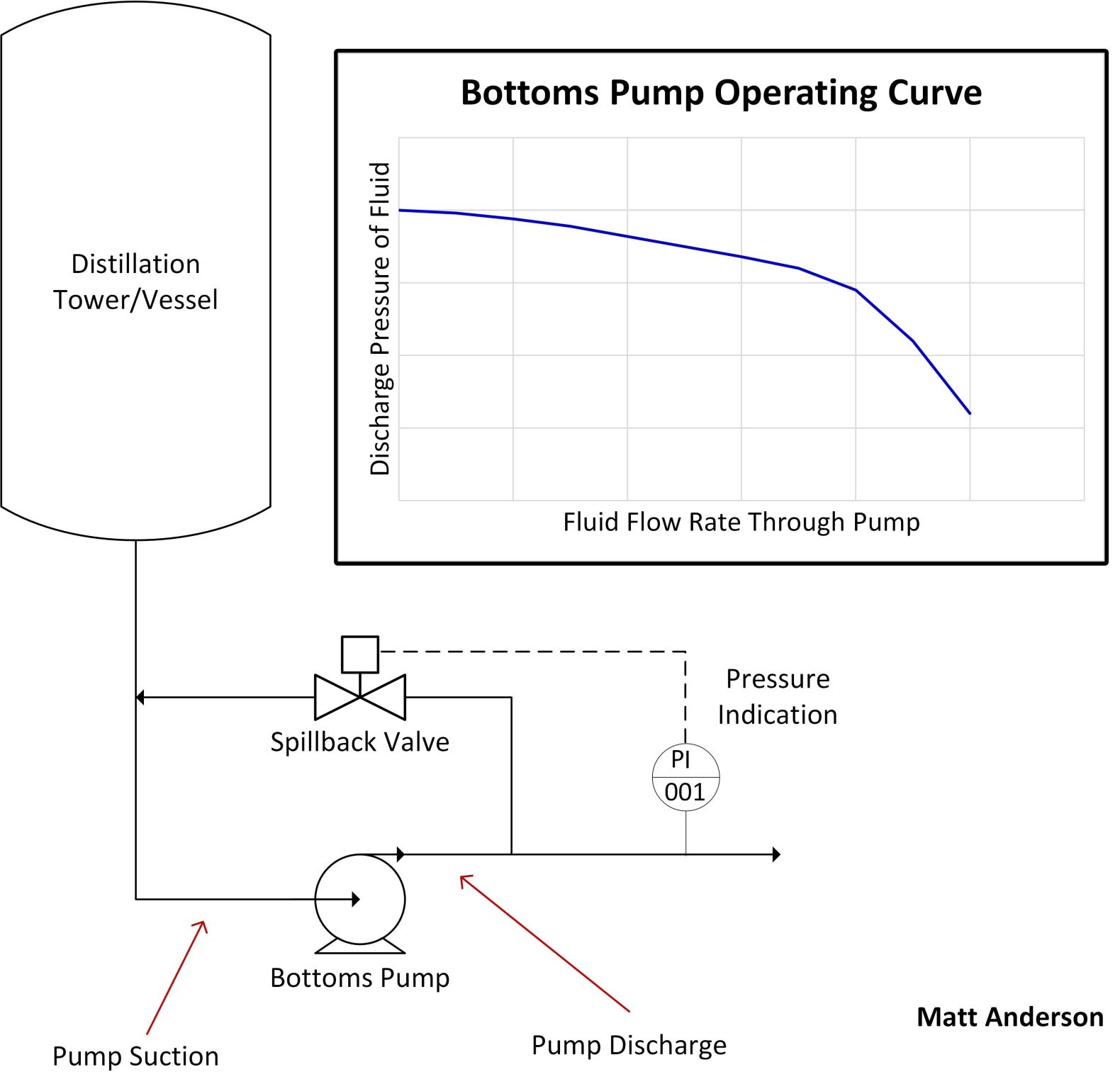
The Control Valve
One version of a pump spillback (pictured in diagram) has a control valve on the spillback line that adjusts based on the pump discharge pressure. If the pressure increases past a setpoint, then the valve will open.
The Pump Operating Curve
To understand why this works, look at the pump operating curve. Numbers are not included because it is only the shape of the curve that is important for understanding how the pump spillback can operate effectively.
The key concept is that as the pump flowrate decreases, the discharge pressure increases.
Therefore, the flow rate and discharge pressure are related. The setpoint of the spillback pressure control valve is designed for the pump to always operate above its minimum flow. As the spillback valve opens, the pressure will decrease because the flow through the pump increases.
Pump FAQs
Q: What is suction and discharge?
A: The inlet is called "suction" and the outlet is "discharge".
Q: To stay above minimum flow, can't you just adjust the pump speed?
A: The vast majority of pumps in process facilities are direct-drive and coupled to a single-speed motor. This means that you cannot adjust the speed of the pump to change the flow. The flow is normally controlled by the opening and closing of control valves.
*Actual pump curves have "feet of head" (in customary units) instead of discharge pressure. Really, it isn't the discharge pressure, but the differential pressure caused by the pump.